Notes from the author
The purpose of this series of entries "Explain Like I'm Five" is to simplify concepts in a way accessible for anyone without a background on the topic. The idea comes from a subreddit with the same name and purpose.
The posts deliberately follow a lie-to-children model, where ideas are first presented in a technically inaccurate but helpful form, to be refined later on.
Feel free to contribute, revise, or give feedback in the comments section. They are more than welcome and will help deliver quality content!
What is Optical Camera Communications?
Optical Camera Communications is a technology that uses LED lamps, e.g., stand lights, floodlights, and screens, to send data to camera devices, e.g., smartphones, laptops, vehicle dashcams, and many more. The transmitted data can be of any kind, the user location in a building, marketing promotions, access codes, network states... From the user's perspective, he has just to point the camera at the light, and the communication will be started.
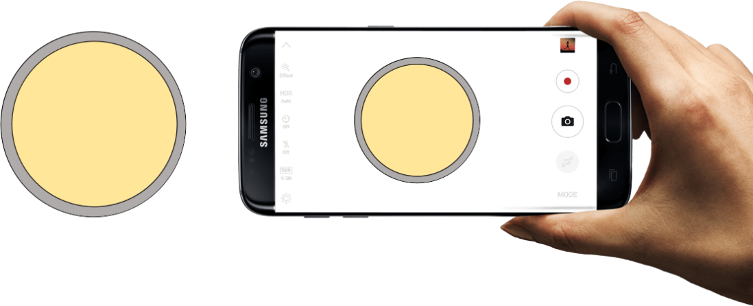 Basic scenario where the user points the camera to a circle lamp.
Notes If you feel comfortable with theory or are looking for examples, go to the last section, where I have uploaded some images and videos showing the OCC technology.
...So... wait, how cameras and LEDs can talk to each other?
Well... Said like that sounds a little bit confusing. Taking apart the communication aspect, it is well-known that cameras receive light from a specific direction to create an image. Hence, when the camera points to a lamp, it captures its light for a short time and generates a picture where it can be seen. This lamp can have different states in the images; it may be turned on and illuminating, off and practically dark, or changing its color from red to green (as an example). Those states can be assigned to different chunks of data (or bits), which we call symbols. So when the LED appears in the image with a particular state (illuminated), we can translate it to the corresponding bits. In simple communication systems, the light turned on corresponds to the bit 1 and 0 otherwise. So the idea is to record an LED lamp over time and capture how it changes between states to decipher the information it transmits.
Interesting... but what about speed? How fast can an LED change its state?
That's a great question! Indeed the LED can change their state very fast. However, if the LED shifts at high speed, it can happen that the camera is not fast enough to capture all the states and lose some of them. In fact, cameras are very slow at capturing images. They usually record videos with excellent resolution at 30 frames (or images) per second, which means a camera can deliver up to 30 photos every second. In summary, If the LED shifts faster than we can record, we will start losing data. In this example, the light can vary up to 15 changes per second.
...Wow! Then, is the communication fast or slow?
Well... it depends. It depends highly on the number of LED states (symbols) we define at the start. We could have relatively fast communication if we could differentiate between many symbols (red, green, blue, off, on, partially red, and so on...). Still, there is always a limit to the number of different discriminable states.
Alternatively, we could increase the speed if we use simultaneously another lamp or transmitter, for example, and split the data between them. Think about that, two transmitters could provide a communication link that is two times faster.
But let's be honest. Conventional radio receivers can detect even more than 1 million changes per second. So these devices are extremely limited in speed because of the camera's frame rate. But there is a much faster approach if we use rolling shutter cameras.
Global shutter vs. Rolling shutter cameras
Now that you have a light sense of how we can receive data using cameras and LEDs, let's rebuild the concept using adequate terminology.
The camera I was referring to uses a specific image acquisition mode called global shutter. The acquisition mode will tell us how the camera acquires the image. In this mode, while taking a photograph, all the pixels of the image sensor is exposed to light simultaneously.
Let's break down this a little (if you know how cameras work, step this paragraph). Cameras contain an image sensor that is in charge of converting light into images. To do this, the image sensor is composed of a matrix of n-by-m photodiodes or photoreceptors (grouped in pixels). Each photodiode converts light coming from one specific direction into an electric current. Intense light generates intense output currents. The output current is then measured and assigned a value in a way that higher values refer to higher currents, thus higher luminous intensity. In the end, the camera hardware assembles the image using the overall pixel values obtained.
However, there is another image acquisition mode called rolling shutter. In this mode, the image sensor is exposed sequentially row-by-row of pixels in an overlapped manner. First, the top row of the camera starts the scanning, then the next one up to the final bottom row. This acquisition can lead to artifacts we can see when recording moving planes' propellers. This distortion effect is caused by the propellers' motion while the camera is taking a photograph. This video provides more information about this effect.
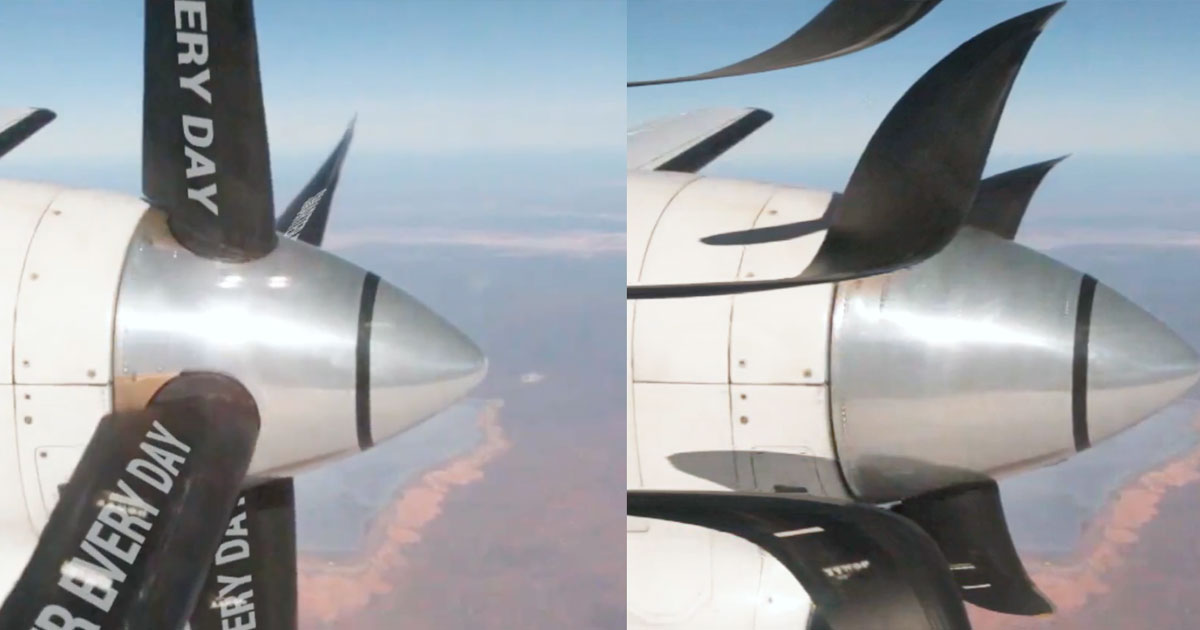 Rolling shutter effect after taking photos of a moving plane's propellers.
This acquisition mode can be used to increase the LED switching speed. In this acquisition, each row samples the LED brightness at different times, generating an image with numerous horizontal stripes with different intensities depending on the LED brightness when the row was activated, as seen in the following animation.
Add animation
So we arrive at the following conclusion. Rolling-shutter cameras allow us to increase the switching speed of the lamp and, hence the communication speed.
Still, this is a very ideal scenario. Actually, we must tweak some camera parameters to achieve these results: the camera's exposure time. But we will discuss this in another post.
It is time for examples!
Now it's time to explore some visual examples of actual experiments. In all these cases, the LED changes its colors (red, green, and blue) to send different symbols. Highlight that these images are not synthetically generated but obtained from working experiments using a custom-designed LED lamp and a Logitech camera (model C920), as shown in the following picture.
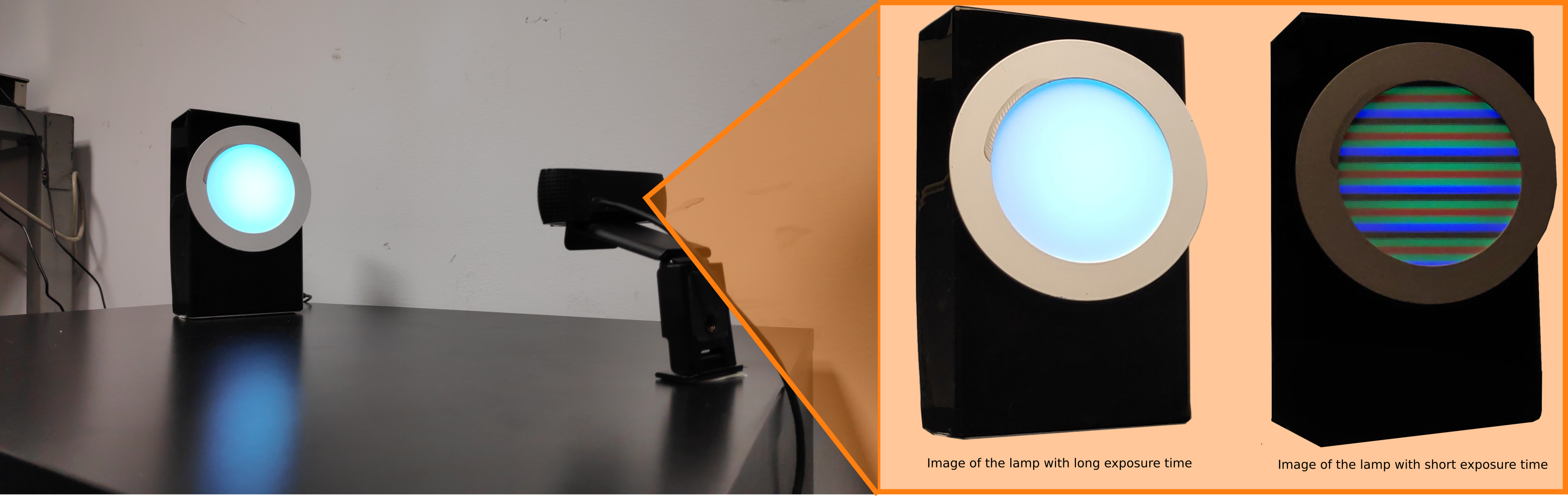 Example scenario where a Logitech C920 is pointing to the custom lamp
With that setup, I have created a composition of real image captures of actual data transmission. Also, I have uploaded a video of my master's thesis defense, where I show how the system performs. The video is in Spanish, and I'm working on uploading English subtitles :D.
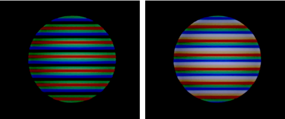 Samples of the data sent by the custom lamp
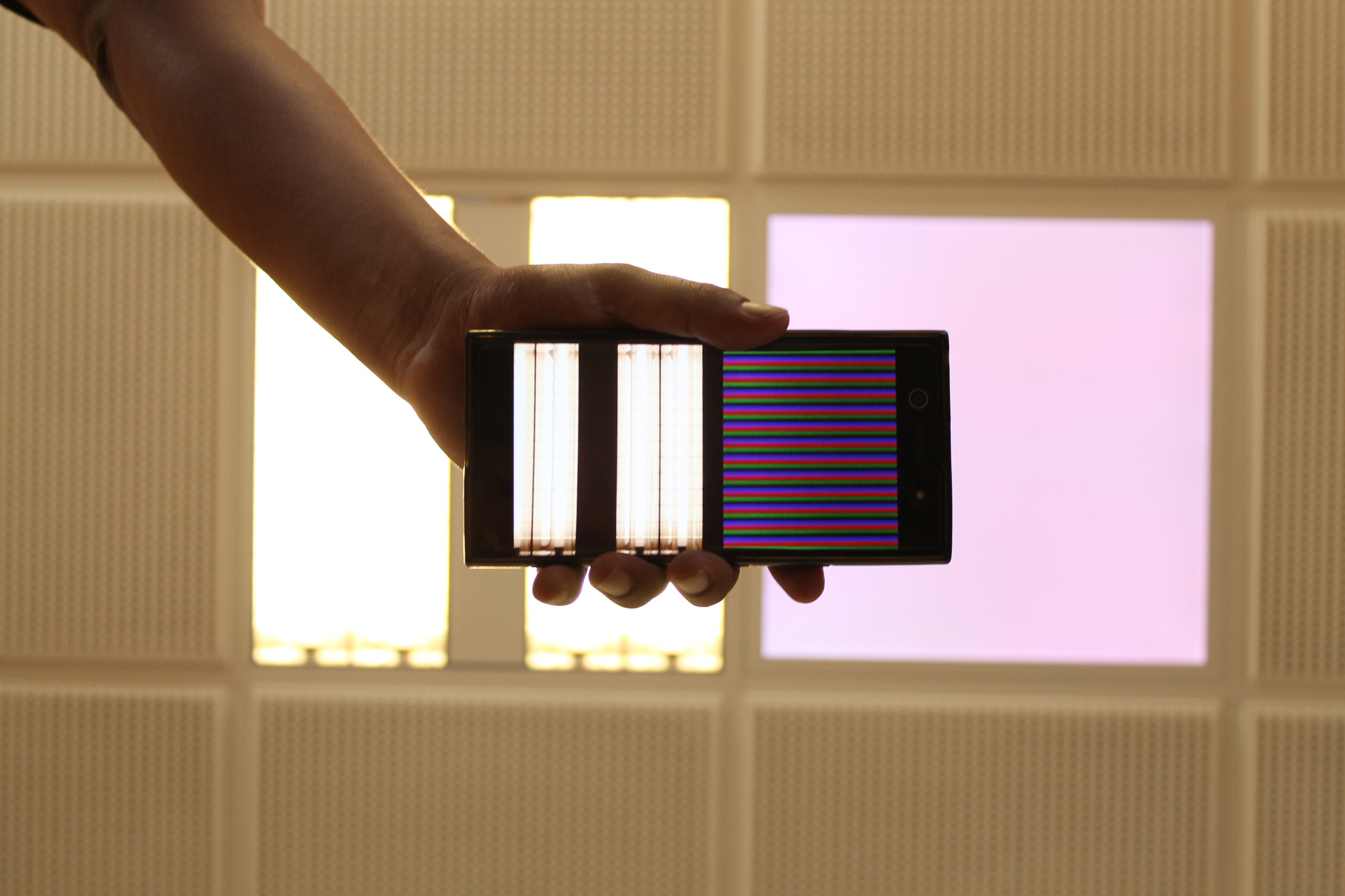
Another example I would like to show you is a ceil lamp installation that we, our team at IDeTIC, deployed in our labs. The following image shows a picture of myself pointing a smartphone camera to the flat panel before installing it.
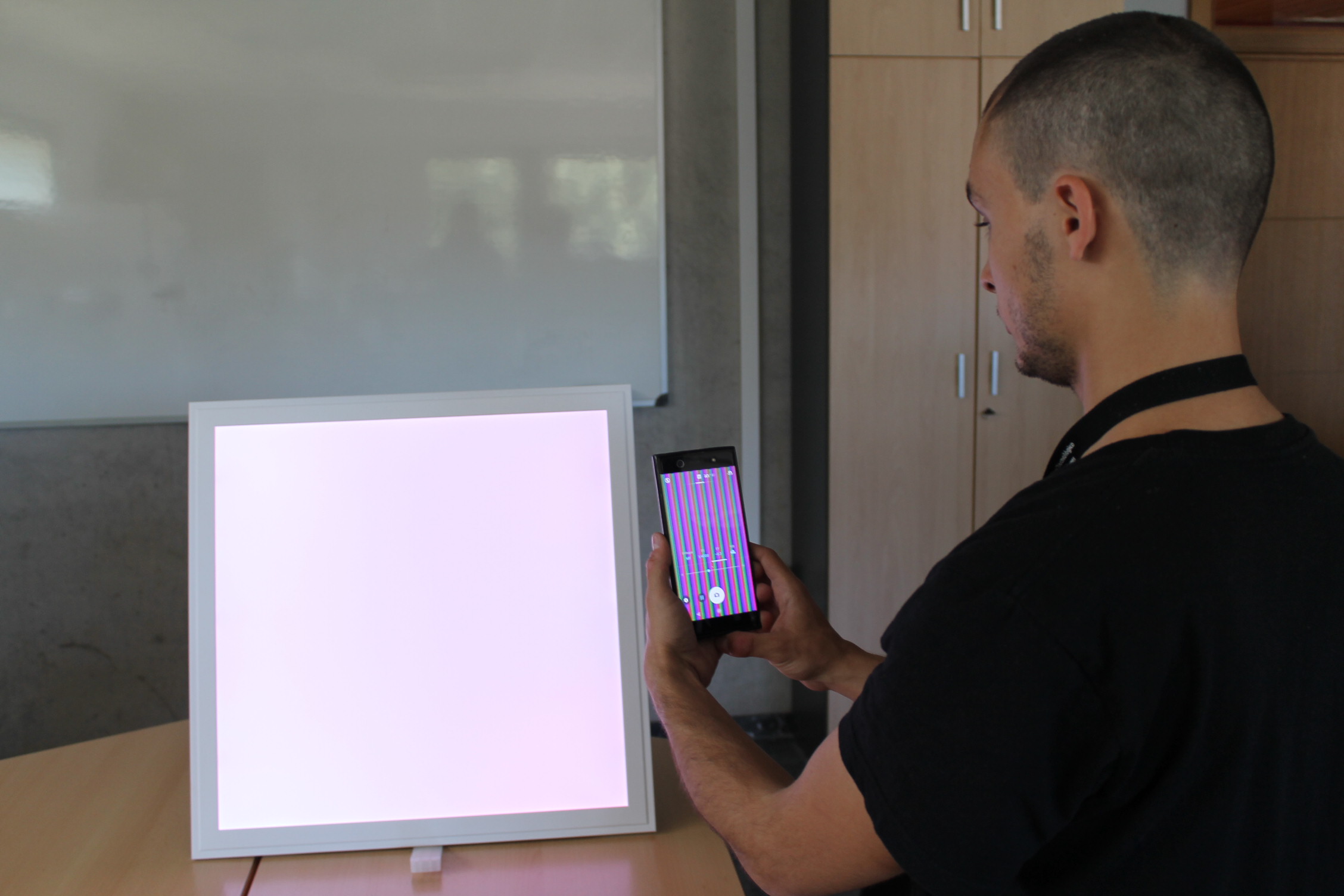 Flat-panel modified to transmit data. The smartphone camera that I hold shows the received data bands.
...How a person sees the lamp?
Optical Camera Communications systems share a common denominator with its parent technology, the Visible Light Communications: simultaneously using conventional lamps for illumination and communications. In this sense, the communication performance mustn't significantly affect the illumination provided by the lamp. In another way, communication must remain hidden from our naked eyes.
Therefore the lamp should switch rapidly with little variances between light states. Otherwise, we will perceive flickering that can be painfully irritating.
In conclusion, the flat panel in the last picture is switching at high speed. To the naked eye, it looks uniform without variations, as shown in the image. However, the smartphone camera with a short exposure time can detect the fast changes the lamp is undergoing.
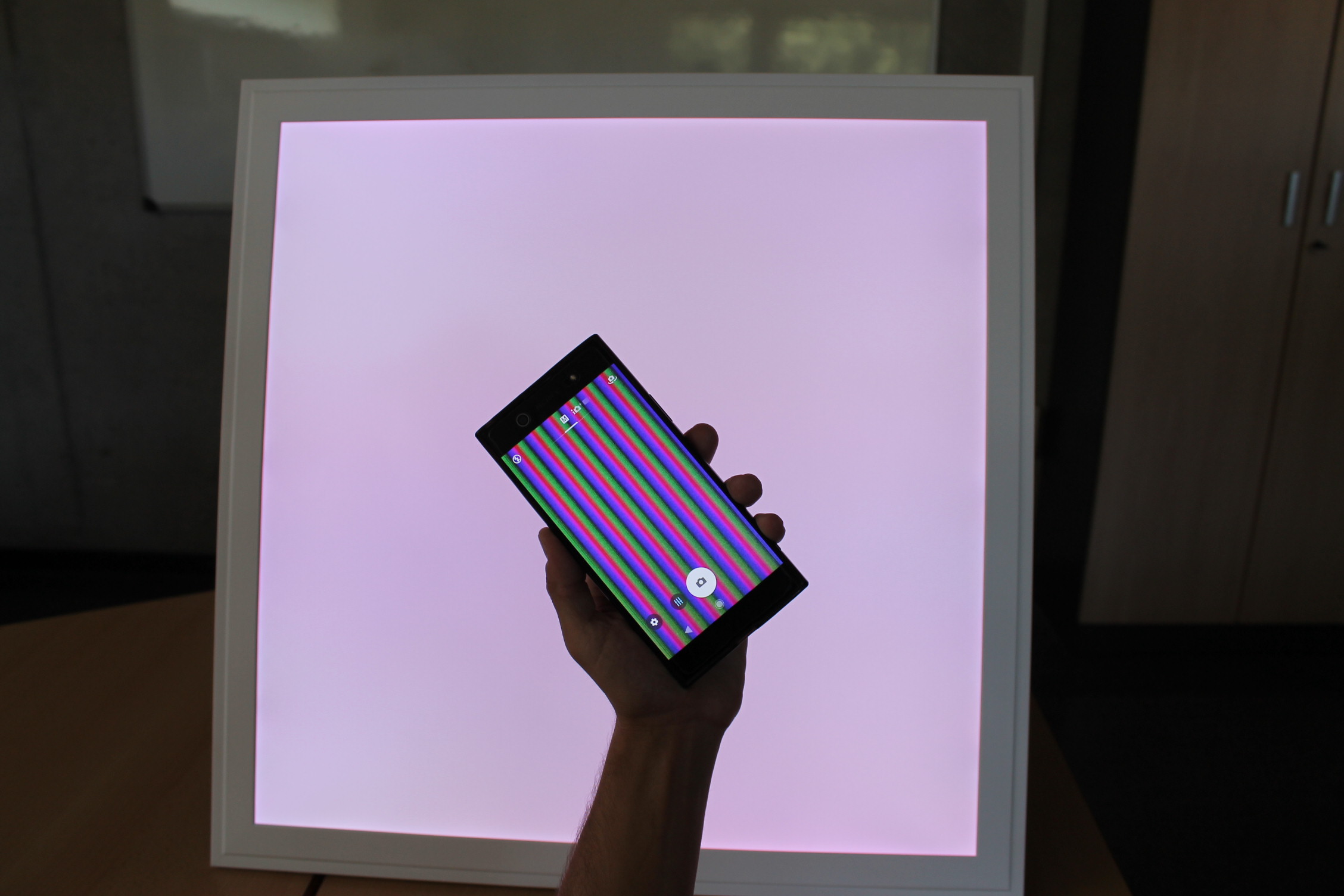 Flat-panel modified to transmit data. The smartphone camera that I hold shows the received data bands.
Here, there is a real-time video showing the transmitter lamp's operation.
For more video examples, check the "VLC for Industry 4.0" project in the projects category.